calligraphy by herald
Overview
Herald is capable of precise actuation along three axes of motion: two in the plane of the paper, and one rotationally up from the paper. Each axis is controlled by a stepper motor. The axes are fully coupled so that the machine is as compact as possible and the pen moves over the page as a hand would.
Herald is primarily made of welded aluminum and also incorporates ABS plastic in various support structures. The base dimensions are 18" x 22". The x and y axes (in the plane of the paper) use eight-start ACME fast-travel threaded rods and nuts for actuation. These axes are supported by drawer slides that function as linear bearings. For the z-axis (up from the page), we approximated the linear up/down motion of a hand by using a system of gears to rotate the pen up and down from the paper.
Mechanical Design Process
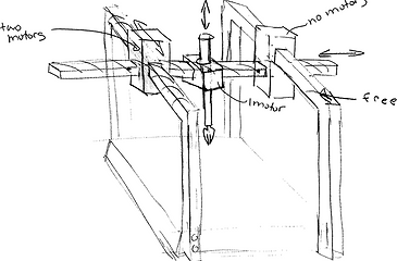
We began by creating concept sketches. Some examples are pictured below.
After exploring different methods of coupling our axes through sketches, we decided to couple all three of our axes because it would produce the most compact machine. We also decided to use threaded rods to actuate our x and y axes because of the rigidity and precision they provide. We considered using a timing belt but we were worried about the stability of that system. The final big decision we made after creating our sketches was to use drawer slides in both the x and y axes. These support the weight of the gantry in the y axis and the weight of the print head in the x axis. They also act as linear bearings and reduce friction, which makes it easier for the stepper motors to move the axes without slipping, which would reduce the precision and quality of our writing.
Once we made these decisions we created a proof-of-concept CAD model in SolidWorks, which ended up being very similar to our final system.
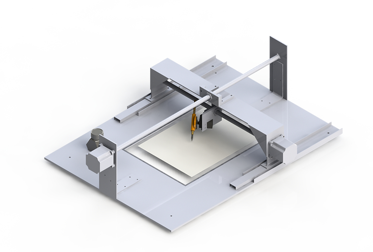
Once we got our basic ideas into CAD, we were able to finalize the specifics of our design. At this point, we saw some of the flaws in our design which led us to include gussets in the x and y axes to prevent any wobble that would affect our precision. Our z axis was finalized last, as it was directly affected by the other two axes. A render of our final CAD model and a close-up of our z axis can be seen below.
One of our final changes was the inclusion of larger, sturdier gussets in both horizontal axes. The y axis gussets are made from ABS plastic and the x axis gussets are welded aluminum plates. We also changed the location of the y axis rod in the final design. We wanted to prevent the gantry from torquing, which would make it catch, so we shifted the rod and motor sideways to be positioned at the center of mass of the gantry system. (This center of mass is not in the middle because of the stepper motor on one side of the gantry.) Finally, we finished design of the z axis, a print head that contains a stepper motor, gears, and a fountain pen. The stepper motor is connected concentrically to the smaller 14-tooth gear which rotates the 96-tooth gear, giving us more precision in the z axis. The print head is held at a specific angle, which we determined by studying the angle at which people hold pens while creating calligraphy. The pen is also held onto the large gear at a different angle determined through the same method.
Once the CAD was completed, we fabricated the machine. Other than the welding on the gantry, all parts were made on a mill or other shop machines and assembled by the mechanical team. The biggest issue we faced in turning our CAD model into reality was alignment of the stepper motor, threaded rod, and threaded nut on the x and y axes. These holes had to be perfectly concentric in order to minimize friction and produce the smooth, reliable motion we required. Although we had planned all of these locations in the CAD model, we could not expect that level of precision in real life. We therefore had to make some adjustments of the threaded nut placement to correct this problem.
Finally, we ended up with the robust, precise, and fast system that we originally set out to produce.